Mechanical ventilator manual link designed: https://drive.google.com/file/d/1uRV9ktVYHOwRvqs9B8ZddRuZ2AVFL2I7/view?usp=sharing
Mechanical Ventilator
BackGrounds
A ventilator is a machine designed to mechanically move air in and out of the lungs to intermittently or continuously assist or control pulmonary ventilation, This device is primarily used in intensive therapy to help improve the patients breathing by regulating the flow of gas in the lungs.
Objectives of the design of a Mechanical Ventilator
- Supply control of ventilation.
- Enable the exchange of gases.
- Reduce respiratory work.
- Facilitate muscle recovery (weaning).
- Allow sedation, anesthesia
Basic Concepts
 |
| Figure 1: general scheme of operation of a uci ventilator |
Mechanical Ventilation Modes
Conventional Ventilatory Modalities:
- Assist-Control Ventilation (ACV) : Total assisted-controlled mechanical ventilatory support is the most basic form of MV, it is used in those patients who present a considerable increase in ventilatory demands and who therefore need total replacement of ventilation. The assisted-controlled modality allows the patient to initiate the cycling of the ventilator starting from a preset value of respiratory frequency (f) that ensures, in the event that this one does not make inspiratory efforts, the ventilation of the patient.
- Synchronized Intermittent-Mandatory Ventilation (SIMV): The synchronized intermittent mandatory ventilation allows the patient to perform spontaneous breaths interspersed between the mandatory cycles of the ventilator, the word synchronized refers to the waiting period that the ventilator has before a mandatory cycle to synchronize the inspiratory effort of the patient with the insufflation of the ventilator. When used with high f covers the patient's ventilatory demands, being comparable to conventional assisted-controlled ventilation. Used with low frequencies, the SIMV allows the progressive disconnection of the Mechanical Ventilation (VM).
- Pressure-Controlled Ventilation (PCV) - Pressure Support Ventilation (PSV): It is an assisted modality, limited to pressure and cycled by flow, which modifies the spontaneous ventilatory pattern, that is, it decreases the respiratory rate and increases the circulating volume. The ventilator provides a ventilation aid, programmed from the support pressure level. The pressure remains constant throughout the inspiration, and in parallel the flow decreases progressively until reaching the level that allows the start of expiration. This partial support modality is widely used, since it allows to synchronize the respiratory activity of the patient with the ventilator when responding to changes in the patient's ventilatory demand. In addition, it preserves respiratory work and reduces the need for sedation and healing, thus facilitating the disconnection of the VM.
- Peep: Positive end-expiratory pressure (PEEP) is a mechanical technique that is often used when ventilating an unconscious patient. This technique includes the addition of a quantity of pressure in the lungs at the end of each breath. The patient's ventilation process causes a degree of desufflation in the lungs; between breaths, the lungs contain less air than usual. By adding positive pressure at that time, we try to reinfuse the respiratory tract.
- Continuous Positive Airway Pressure (CPAP): It is a spontaneous breathing modality with PEEP, in which a supraatmospheric pressure is maintained throughout the ventilatory cycle. The flow must be high to guarantee a high gas supply, higher than the requirements of the patient and small pressure oscillations (<5 cm H2O) so as not to cause excessive respiratory work.
- Airway Pressure Release Ventilation (APRV): It combines the positive effects of continuous positive airway pressure (CPAP) with the increase in alveolar ventilation obtained by the transient decrease in airway pressure from the level of CPAP to a lower level. Ventilation with pressure release provides long periods of insufflation, interspersed with brief periods of pulmonary deflation. It is a mode of partial ventilatory support cycled by the ventilator or by the patient and in which during the period of insufflation the patient can breathe spontaneously. Its main advantage lies in the fact that the pressure in the airway can be set at a modest level, and furthermore as the pressure is maintained during a longer period of the respiratory cycle an alveolar recruitment occurs. In theory, short periods of deflation do not allow alveolar collapse, but it is sufficient for the exchange of gases not to be affected by the CO2 clearance.
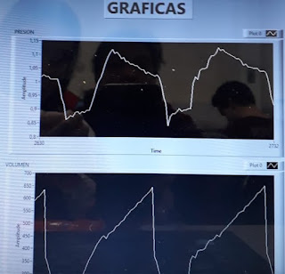
Respiratory Curves: in the different ventilation modes mentioned above, flow, pressure and volume curves are used in time to have a detailed analysis of the operation of the mechanical ventilator.
 |
| Figure 3: Respiratory Curves (flow,pressure and volume) |
According to figure 3:
Flow Curve: Starts according to the flow pattern selected at the beginning of inspiration. In assisted or pressure-controlled respirations, the flow is slowed and in volume-oriented modalities, quadratic flow is generally used. At the end of the inspiration, the flow becomes 0, and is inscribed below the X axis, which represents the expiration that constitutes the most important portion of the curve, it must be linear starting from the maximum expiratory flow to the baseline, before of the next breath (expiratory pause time). In the different ventilation modes mentioned above, flow, pressure and volume curves are used in time to have a detailed analysis of the operation of the ventilator.
Volume Curve:Should be correlated with the previous ones, indicates some of the problems already mentioned in the previous curves.
Pressure Curve:This should ascend smoothly. In ventilations controlled by the ventilator, the pressure curve starts from the final expiratory pressure and in those triggered by the patient, an initial negative inscription indicates the inspiratory effort. In the pressure curve the autopeep is not observed because it is disguised, it must be suspected when the inspirations begin very early on the expirations (high respiratory frequency) or the patient has conditions having autopeep (bronchial asthma, COPD, small caliber tube).
Design
Interface Desing
 |
| Figure 4: Design Control panel |
The design of the mechanical ventilator for adults was developed through the implementation of an interface called the control panel, where the ventilatory control modes are selected, parameters are entered and the respiratory curves are observed. everything named above is implemented in the LabView programming software.
Electric Diagram
 |
| Figure 5: Electric Diagram Mechanical Ventilator |
T


No hay comentarios.:
Publicar un comentario