PERISTALTIC INFUSION PUMP
BackGrounds
 |
| Figure 1: Infusion Pumps |
The infusion pump is an
electronic device capable of providing, by means of its programming and in a
controlled manner, a certain substance by intravenous (para-arterial infusions)
or oral (enteral infusions) to patients whose condition requires it. The use of these devices is very important because they reduce the percentage of human errors in the intravenous drug supply, regulating in a rigorous way the flow of liquids inside the patient under a positive pressure generated by the pump. The pumps provide greater accuracy and safety in the infusion of drugs than traditional flow control methods (controllers), are capable of exceeding small occlusion pressures, can overcome the resistance of the antibacterial filters and arterial lines to the infusion and They can infuse drugs with great precision at very low speeds. To assess the competitiveness of a device, characteristics such as accuracy in the amount of substance infused (normally with errors of 5%), accuracy in the established time interval, ease of use and programming, safety alarms are taken into account. etc.
Feeding
Normally the pumps work both with the power supply of the electric network and with internal battery. If the pump runs on the mains and is disconnected or fails, it automatically switches to battery power. Before reaching the exhaustion of the battery the pump gives an alarm signal.
Drive mechanism
Part of the team responsible for carrying out the pressure in the administration set to achieve the perfusion of the liquid. It is usually composed of a motor controlled by a microprocessor that generates impulses proportional to the perfusion flow. The motor normally moves a piston or peristaltic mechanism that performs the pressure on the administration set.
Venocolysis device
 |
| Figure 2: venoclysis device and its parts |
Its use is in the medical area since it is a device intended to enter intravenously, either peripheral or central, the continuous infusion of fluids. Normogotero that is made with different types of medical grade plastic and whose main feature is to provide a drip between 28 and 32 drops per minute.Microgotero that besides having medical grade plastic, has a metal cannula that offers a drip of 56 to 64 drops per minute.
Types of Infusion Pumps
Peristaltic Pumps
 |
| Figure 3: Parts of a Peristaltic Infusion Pump |
They work by pressing a flexible bag or tube to produce movement of the liquid that is inside a container. Two modalities can be found within this classification, linear peristaltic pumps and rotary pumps. Linear peristaltic pumps have a line of finger-shaped discs that compress the tube into a wave form of continuous motion, forcing fluid out of the container toward the patient. Rotary peristaltic pumps use a rotor that presses the liquid into the tube through rollers through a semicircular passage.
Syringe Pumps
 |
| Figure 4: example syringe pump,https://www.pardell.es/curso-bombas-.html |
Preferred when it is required to supply low volumes and low flow rates. These pumps push the plunger of the syringe at a controlled rate to deliver the substance to the patient. The supply rate can be continuous or in steps that provide boluses in a certain time. The syringe is placed in the pump with the plunger fitted on the plunger holder. As the embolus advances, the syringe empties.
Rotating Peristaltic Pumps
It is perhaps the least accurate of all pump systems and is not generally used in the intravenous application of medications. Its use is focused more on the administration of food, as is the case of parenteral nutrition. The rotary pump is also widely used for the infusion of blood in the operating room, during the implantation of a bypass or in blood banks for the processing or separation of plasma cells.
Implantable Infusion Pump
 |
| Figure 5: Implantable Infusion Pump http://www.sonivega.com/ELECTROMEDICINA/Paginas/BOMBAS_DE_INFUSION..html |
Security - Alarms
The infusion equipment must have minimum safety measures:Accuracy of operating data: the equipment must maintain the accuracy established by the manufacturer or higher. The most usual precision values are between 3 and 10%.
Opening maintenance rate, TMA (also known as MVA, maintenance of the Open Vein): these are predetermined low values of the perfusion rate in order to keep the patient's duct open.
Maximum perfusion pressure: maximum pressure that the equipment can generate under conditions of total obstruction at the end of the patient's duct.
The minimum alarms that a pump must carry are the following:
- Food Alarm
- Obstruction Alarm
- Air Detection Alarm
- Empty Container Alarm
DESING
electrical diagram:
figure 6 electical diagram
For the design of the infusion pump a peristaltic motor is used, which from the control of PWM sent from the arduino, which allowed the amount of fluid to be released, for this the characterization of the motor was made as shown in figure 6 On the other hand, the mode of operation of the prototype carried out consisted of entering the parameters of volume and time, and from this, determining the flow that would be released by the motor, the control of the exhausted liquid alarm was made from the use of electrodes that when in contact with the fluid closes the surgeon and sends a 1 to the arduino and when the liquid is finished the circuit is opened causing a zero to be sent to the arduino allowing it to be detected when the fluid runs out, On the other hand to stop the bubbles was made use of a barrier sensor that allowed analogously to determine when there was one.
RESULTS
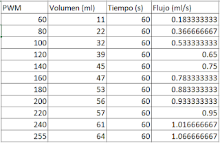
After making the code and the model began to relate the value of PWM with the flow, to do this we post the volume pumped by the engine in a given time (one minute), giving the following table (table 1):
 |
| Table 1: Characterization table. |
The points that were obtained after characterizing the motor were related in a linear way, and when tests were carried out, lags of up to 5ml were obtained, therefore, the trend line was changed to an exponential one (figure 7).
 |
| Figure 7: Characterization. |
The fully finished model can be seen in figure eight. To control the infusion pump an alpha numeric keyboard is used, to visualize the information an LCD screen was used. When the pump is connected, the screen shows a selection or start menu (figure nine), from this menu the user will select the volume to enter in a certain time, which determines the flow. According to table 1, the operating range of the pump is between 0.183-1.066 ml / s. The pump only goes into operation when the time and volume values are entered.
 |
| Figure 8: Finished model. |
 |
| Figure 9: Start Menu. |
CONCLUSIONS
- The infusion pumps generate mechanical pressure to move the fluid through a tube to the patient's vascular system, helping to administer the fluids with more precision, this causes a greater accuracy in the drip rhythm than the gravity systems, saving time since it is not necessary to be regulating the drip flow.
- The infusion pump precisely administers the infusion despite: the patient's movement, patient's arm position, inadequate catheter fixation, catheter bracing or equipment conveyor tubes, resulting in optimal administration, generating an early recovery decreasing patient complications.
- To generate the alarms in the code, interrupts can be used. To perform the alarms in this case, we used conditional if nested within a for cycle in which the main function is executed.
BIBLIOGRAPHY
- Bowcutt M, Rosenkoetter MM, Chernecky CC, Wall J, Wynn D, Serrano C. Implementation of an intravenous medication infusion pump system. J Nurs Manag 2008 03;16(2):188-197.
- Bombas infusión (Apuntes Electromedicina SEEIC), Xavier Pardell, 2012.


